STEEL BARREL
STEEL BARREL PRODUCTION LINE
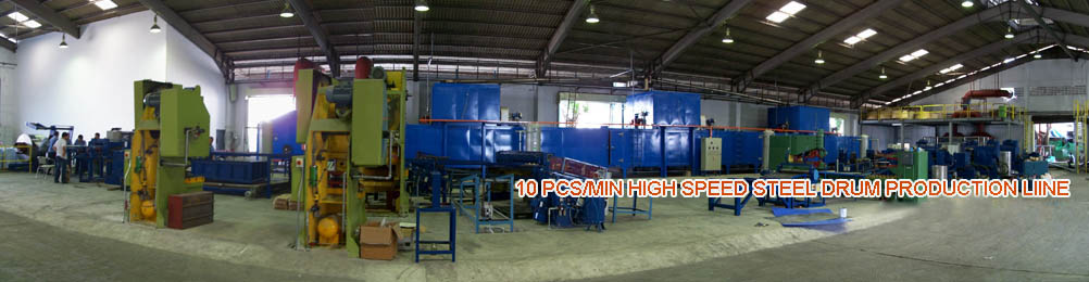
- 10PCS/MINUTE HIGH SPEED STEEL BARREL PRODUCTION LINE
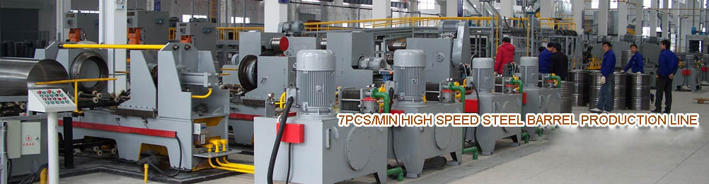
- 7PCS/MINUTE HIGH SPEED STEEL BARREL PRODUCTION LINE
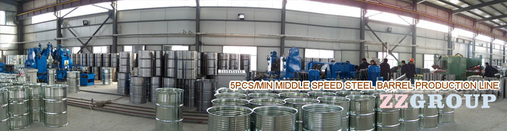
- 5PCS/MINUTE MIDDLE SPEED STEEL BARREL PRODUCTION LINE
- 1PCS/MINUTE LOW SPEED STEEL BARREL MACHINERY
Barrel Cover Punching Machine
Fourth, the production process for the top end of the barrel
The top of the bottom of the steel barrel production including stamping ( blanking stamping ) , pre-roll glue , sealer assembly and other processes. The top end of the barrel is the use of stamping die stamping , work out in the press .
1 , press
There are typically three types of stamping equipment , namely crank presses, screw presses and hydraulic presses . Drums produce the most commonly used is the crank press . Crank presses by the body , transmission, clutch , brakes, crank slider mechanism and the lower stretch mats and other components of the . Figure is a schematic structural diagram crank press .
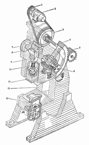
Inclinable press Schematic
Crank press work, drive motor through the flywheel crankshaft rotation , the crankshaft axis line with the axis of the crank offset an eccentricity r. Connecting rod is connected to the crank and slider parts. Connecting rod bearings and crank , connecting rod and the slider is articulated through ball . Thus , when the crankshaft rotates the slider up and down reciprocating linear motion , which is the crank - connecting rod mechanism . This mechanism not only make the rotary motion into a reciprocating linear motion , but also from the force amplification, ie, an increased force , the slider in the lowermost position, the greatest pressure.
Stamping die fixed upper mold lower surface of the slider , the lower mold plate fixed to the plane of the table , therefore , moving the slider up and down every time a stamping operation is complete . Although the linear reciprocating motion of the slider crank rotational movement is facilitated , but also uniform rotation of the crank , but the slide in various points in its travel speed is not the same . Downward stroke of the slider , the slider in the upper dead point the speed is zero. Slide downward movement continues , which increased to a certain maximum speed , reaches the bottom dead point, the speed drops to zero again . Stroke in the upward and downward stroke , as the moving speed of the slider from zero to a maximum and then repeated by the maximum to zero this range.
Presses the flywheel has a relatively special role. Presses for power is an intermittent machine , crankshaft rotation one week once a punching slider , but the actual working stroke only a small part of the whole trip , and in this small section of the trip was a lot of work to do , the nature of the impact load is . Acting in accordance with the requirements of the press , to select a very large motor , but such a large motor , only work in a very short time before full load , in most of the time the air-way load is small , so that it will cause large waste, in order to solve this problem flywheel settings .Flywheel mounted on the first stage is usually a high-speed shaft of the gear transmission , the power of this motor can be greatly reduced , because the slider does not move when idling motor driven flywheel , the stored electrical energy supplied .Stamping parts in the short period of time which depends mainly on the flywheel release energy. The speed is reduced in a releasable manner . When completed stamping parts , the load is reduced , so the rotation of the motor flywheel acceleration , making the press before the next workpiece to return to its original speed . In this way , the energy required for punching workpiece , which is the peak load can be substantially reduced.
Clutch and brake in the press has the effect of stopping the rotation of the flywheel is not the case , start or stop the press . Clutches and brakes are generally provided in the flywheel shaft. When the slider is actuated when required , by the control system , disengage the brake , clutch, motor , flywheel rotational motion and energy transmitted through the clutch to the drive gear and the slider. When you need to stop the slider, the control system through the clutch disengaged , brake , the brake flywheel live below the moving parts , so that the press stop . Press the clutch does not always work in a disengaged state, and the brake is always in the braking state.
Slider mechanism including the slider body , shut height adjustment mechanism , balance device , overload protection devices , back feeding device and other components. Slider body is a box -shaped structure , the lower plane has opened a trapezoidal groove or screw holes for mounting the die on the template . Closed height adjustment mechanism is to adapt to different height of the mold can be closed in a bench presses to install and set up. Balancing device is to eliminate the stress between the upper mold part and friction , reducing vibration and noise and settings. Unloading unit 's role is in the slider up their return , the parts out from the top of the mold .Overload protection device is the role of the press in order to prevent the production and prevention of the adjustment process , overload may occur and damage the device.
The role of drawing pad has two aspects, one is in the process of drawing the edges of the sheet metal pressed parts in the drawing process without wrinkles. The second is when the stamping process finally shaped parts from the mold ejection. Drawing pad and a spring-loaded rubber type , there are also pure gas -like and liquid- gas type.
2 , the mold
From the die structure, its main components , varies according to the type die . In the production of steel drums , the structure typical stamping dies are blanking punching , bending die , blanking drawing die , etc., the top end of the barrel stamping mostly blanking drawing die . From process analysis, drawing die blanking blanking by a basic step and a composite drawing of basic processes . Figure is a typical blanking drawing die schematic. It mainly consists of upper and lower template , guide pins and bushings , punch and die , retire feeding device, stop feeding device, pressing device and other components.
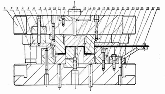
Barrel lid blanking mold structure diagram
Blanking drawing die working process are: care in the blank into the die 21 , 17 and prop blank holder plate 27. Relies on positioning pins 8 and 28 will be a good gauge screw position . Upper die down , by the stripper 4 suppress the blank , and then start blanking punch and die 10 . At this point blank holder 17 by prop rod 19 to suppress the blank tightly to prevent wrinkling when drawing . Return when the punch , binder ring 17 to 15 parts from the top of the punch , card punch 10 , the push rod 13 until the fight hit the press material beams, push the ejector 14 will be drawing the workpiece top out .
Composed of all the parts of the mold , according to its function can be divided into parts and auxiliary process structure structural parts into two categories. Craft structural parts directly involved in the blanks to complete the process and directly interact , including: working parts ( processed directly on the rough parts ) , positioning parts ( used to determine the correct position of rough machining of parts ) , binder , unloading and the material parts. Assist structure parts are not directly involved in the completion of the process , do not directly interact and the blank , only from the mold to complete the process to ensure the function of the mold effects or play a sound effect , comprising: a guide part ( bottom part of the mold to ensure the correct relative position ) , the fixed part ( used for installing the mold parts or to be fixed to the press mold ) , fastening and other parts ( parts and auxiliary connections are tight craft parts ) .
3, the bottom of the barrel top preroll spray process method
Bottom of the barrel top pre-roll crimping sealing process is to ensure the quality and settings. After a pre-roll barrel bottom , can be relatively easily realized only seven Crimping, and because of the simultaneous crimping of pre sealant coating, so that a strong crimp seal performance guarantee. Therefore, the domestic steel drums manufacturers, are top of the bottom of the barrel as a necessary pre-roll process to do .
Pre- roll machine consists of frame, upper and lower platens , curling roller system, transmission , spray systems, control systems, and feeding rack and other components.Figure is a schematic outline pre-roll machine .
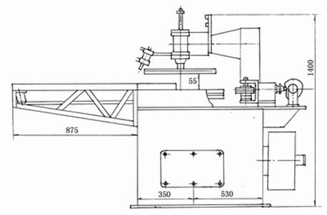
Bottom of the barrel roof structure preroll spraying machine
Pre- roll machine works as follows : the lower plate by the motor via reducer driven gear wheel system operation , work began , the first from the side into the top end of the barrel between the upper and lower plate , the plate cylinder driven by the pressure , the bottom of the barrel ( top ) tightly sandwiched between the upper and lower plate and with the rotation of the lower plate , and then the right pre-roll driven by a cam roller guide rails left by moving toward the top edge of the bottom of the barrel , so that the top edge along the bottom of the bucket wheel preroll rolled up ; in the meantime, a puff of gun barrel sealing glue to the edge of the centrifugal force to move within the arc has been rolled up to form a complete uniform apron , and then turn the cam trough , wheel exit , and then on the plate cylinder moves , the upper plate is moved away from the top end of the barrel . Bottom of the barrel top lose clamping force , the rotational inertia of the driven machine thrown preroll . Then they repeat the above process.
Spray system is composed of plastic storage tanks, guns , pressure gauges, diameter gas hose, pneumatic system and control system components. Compressed air through the gel into the storage tank, the glue in the tank to obtain a certain pressure , and then leads to the glue gun , the gun is provided with a control valve , when the valve is opened, the glue gun discharge begins when the valve is closed, stop the spray gun .Gun control system consists of upper and lower platen control system coordination.
4, the barrel assembly of top sealer
Drums spirals common lock installation method , in the last one had been brief , here we mainly introduce a more advanced method of assembling method - S -lock installation method .
In steel drums containing the goods during transport , often subject to bump or stumble , and bung in the bumps , the most prone to leakage. When we examine the structure of the anatomy , found that the original structure is destroyed lock installed , the sealing performance also will be lost. As shown, the traditional standard screw ring lock ring structure before and after the drop test deformation .
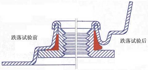
Standard barrel top coil with drop test site before and after comparison chart
In order to solve the structure of bung lock installed fatal flaw , India Technocraft Industries developed the "S" type lock mounting structure , the perfect solution to this problem . Shown as S-type lock mounted spirals diagram of the structure .
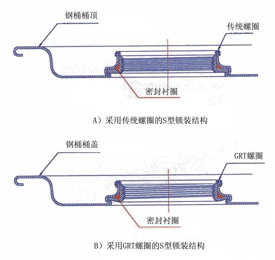
The S- lock mounting structure , since the position is S Plus structure after the drop test , no deformation as in Figure 6 , the lock on the basic structure intact , greatly enhance the sealing performance of barrels . According to statistics , since the lock on structural changes , bung leak rate can be effectively reduced by 90 % or more, in the international transport packaging , important export and hazardous materials with steel drums , have been widely adopted this lock mounting structure .
S-type lock on the production , the use of S-type spirals lock installed special mold to complete , with the same traditional mold production efficiency can be molded disposable locks installed .
Use GRT spirals , using S- lock mounting technology , these two technologies together , bung sealing performance can reach 100 % qualified , bung can basically achieve the goal of zero leakage .