STEEL BARREL
STEEL BARREL PRODUCTION LINE
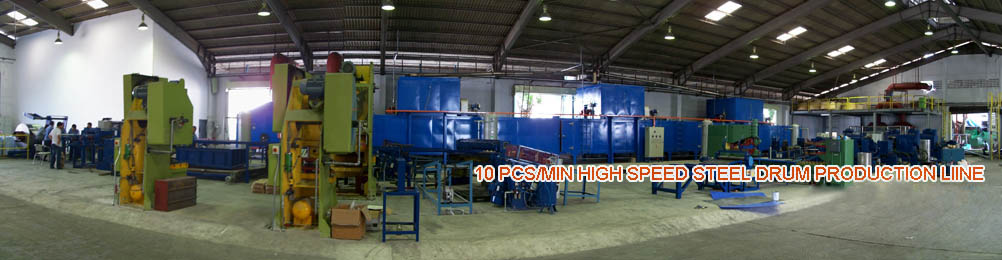
- 10PCS/MINUTE HIGH SPEED STEEL BARREL PRODUCTION LINE
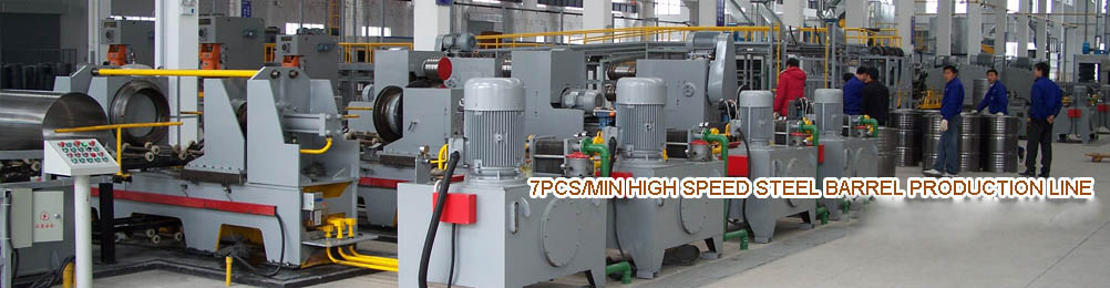
- 7PCS/MINUTE HIGH SPEED STEEL BARREL PRODUCTION LINE
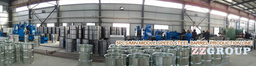
- 5PCS/MINUTE MIDDLE SPEED STEEL BARREL PRODUCTION LINE
- 1PCS/MINUTE LOW SPEED STEEL BARREL MACHINERY
Steel Barrel Manufacturing Technology and Equipment
Section steel drums making technology and machinery
Drums is important packaging containers. Steel drums , with its good strength, corrosion resistance , security, reliability , etc. are widely used in chemical , oil , paint, light industry, food and other industries.
Many different types of drums . There are drums ( steel storage barrels referred drums ) and steel pails . Divided by the service life of light and heavy barrel barrels ; by the structure have closed barrels, open drum and corrugated barrel ( barrel body has an annular corrugated ) , smooth barrel ( barrel body surface finishing smoothing ) . Steel pails with conical (T -type ) and cylindrical (S type ) of the points. Are respectively introduced steel storage drums and steel pails processing equipment.
First, the steel drum manufacturing technology and equipment
Metal drums of a wide range of manufacturing equipment , summed up mainly include: for the manufacture of barrel body, bottom of the barrel ( lid ) , mouth piece bucket , locking hoop variety of general and special machine tools , molds and welding equipment for sealing assembly equipment, leak testing equipment, spraying equipment, cleaning equipment, drying equipment, and a variety of transportation devices. Steel drum major manufacturing equipment , such as the composition and classification are listed in Table 17-1 . Drums manufacturing equipment mainly cutting machine, milling machine, bucket frame molding machines, flanging machines, corrugated machine, bulging tendons machine, sealing machine , leak testing machine ( spot seam welding machine welding equipment, and general same spot seam welding are not listed ) . This section selectively introduce the dedicated machine working principle and structure .
Table 17-1 Main Equipment List of Steel Barrel Production Line
| Type | List |
Working Method |
||
Material Cutting device |
Material Feeder |
|
||
|
Seprate Device |
磁化式、压缩空气式 |
||
|
Suck and moving device |
|
||
|
Slitting Machine |
平刃剪、斜刃剪、圆盘剪、切断模 |
||
|
Conveyor device |
|
||
Grinding Machine |
Grinding and Cutting Device |
|
||
|
Conveyor device |
|
||
Drum frame forming machine |
round drum forming machine - rounding machine |
|
||
|
异形桶框成型机(折方机、胀形机、整形机) |
锥体式、滚轮式、楔块式 |
||
Flanging machine |
Round drum Flanging Machine |
滚压式、挤压式 |
||
|
异形桶翻边机 |
滑块式、滚压式、挤压式 |
||
波纹机 |
|
机械式 |
||
胀筋机 |
|
机械式、气动式、液压式 |
||
Drum Sealing Machine |
圆桶封口机 |
桶体旋转式(机械式、液压式)、桶体固定式 |
||
|
异形桶封口机 |
内轨道仿形式、外轨道仿形式 |
||
Leakage Test Machine |
|
浸水式、皂液式、气压变化式 |
||
( A ) cutting machines
Metal cutting machinery refers to the steel drums for barrel physique , bottom of the barrel ( cover ) plate or barrel hoop strip cut machinery. It includes a variety of shear .
Shearing machine according to the different forms of scissors , can be divided into flat blade shears , helical blade shears, circular shears , vibration shears and shear machine with a cutting die . Which shears with cutting die cut barrel hoop commonly used in the strip . The most used is the flat blade , bevelled and circular shears . In order to improve the cutting speed , improve working conditions, generally through a variety of mechanical or hydraulic , pneumatic and electrical components to achieve automatic feeding .
Barrel physique automatic production line mainly includes cutting shears , sheet feeding device, separator , blower unit and conveyors . Figure 17-19 for the barrel physique automatic blanking lines Fig. The cutting production line work process : first forklift to stack plates to feed the stage, vertical cylinder 2 pass into the air chamber on the piston down, four suction cups on the piston rod blower driven by pressure frame 3 suck on the metal plate stack tight, and then through the valve with compressed air into the cylinder 2 lower chamber , the piston upward, while the separation device ( magnet 16 ) detached single sheet sucked up , and then the horizontal cylinder 1 piston left rows of the plate to attract conveyed forward . Then let the cylinder 2 piston down , pick up the plate in contact with conveyor 7:00 , leaving the suction cups connected within the atmosphere disappear , steel down to conveyor 7 and fed bevelled cutting bed material . At this point upward piston cylinder 2 , a piston cylinder a right line , sucker back into place and re- work .
Figure 17-19 barrels are automatic cutting production line schematic
1 - horizontal cylinder China; - vertical cylinder ; 3 - blower frame ; 4 - sucker ; 5 - metal plate stack ; 6 - feeding station ; 7,9 - conveyor ; 8 - The following scissors ; 10 - under shear plate ; 11 - on the shear plate ; 12 - floating guide block ; 13 - the scissors ; 14 - transmission wheel ; 15 - activities positioning stopper ; 16 - magnet
When fed shears to cut steel plate shear position, the conveyor 7 stops , activities positioning stopper 15 from the conveyor belt to float upwards , then downwards on scissors cutting material . Once the sheet to be sent over the cutting edge shearing blade position , the conveyor belt will automatically stop , stopper 15 rises , then invert the drive roller 14 , so that the stopper plate positioned after the move stops , proximity switch ( notdraw ) signals , and lower down on the scissors 13 8 pairs of steel scissors cut . Followed up on the scissors back position , the conveyor belt 7 continues to run , will have to cut ( one or both sides ) steel rushed conveyor 9 . On both sides of the conveyor 9 , each a circular shears , cut side near the disc when the steel plate shear , stop the conveyor , then floating beneath the guide block 12 rises from the conveyor belt and push forward plates, on both sides of the plate the upper and lower circular shears shear 10 and 11 . After shearing bucket conveyor 9 physique will send off shears and complete a cutting board .The production line is to be completed by a trilateral barrel plate shear .
( Two ) Edging Machine
Edging machine from the grinding device and conveyor components. Nowadays a good job sheet sent conveyor , conveyor sides ( also unilateral ) with grinding apparatus ( grinder ) , the conveyor will be two sides of sheet metal ( or side ) polished finish . Then sheet continue to complete another 90 ° rotation on both sides polished finish . In the sheet conveying device by a plurality of pairs of roller holder , to prevent transport grinding sheet deformation . This mechanical grinding side once , and once grinding on both sides , there are four sides of a conveyor grind respectively . After edging to curling sheet welding, welding using resistance welding, resistance welding method with the same aforementioned .
( Three ) bucket frame molding machinery
Barrel frame molding machinery refers drums barrels are used to accomplish a variety of special machine molding process and apparatus . Of its kind with the barrel and forming methods vary. Molding machine for round barrel is rolling machines ; profiled barrel body for more types of molding machinery , there are folding side machine , bulging machines, shaping machines.
1 Rolling Machine
Rolling machine is rolled into a cylindrical barrel physique machines. Since barrel curling physique is staggered configuration between three rotating rollers , so rolling machine is also known as a three-roll bed. Rolling machine rolls on three positions have certain requirements , lower roller upper roller located above and slightly backward roll direction offset a short distance. Work rotating upper and lower rollers roll the barrel physique backward direction, when the board is in contact to the rear end of the roll , because the rear roller prime line is higher than the upper surface of the upper surface of the lower roller prime line, forcing the barrel physique curl upwards until its entire length to be rolling .
Rolling machine, the rear roller position is adjustable to suit different diameter barrel frame molding. The gap between the upper and lower rollers is adjustable to accommodate different thicknesses of sheet metal barrels are rolling . Figure 17-20 shows a schematic view of rolling machines work . When the bucket conveyor a physique right transmission, and the upper and lower feed rollers , the upper and lower rollers rotating barrel physique make moves backward rolls , plate roll after hit after the end of the barrel is a continuous upward curl physique until the barrel physique completely rolling .The barrel has been rolling box is Divider 4 block to the right , through the swash plate 5 into the next process of the conveyor.
Figure 17-20 Schematic rolling machines work
1 - conveying device ; 2 - roll ; 3 - Top roller ; 4 - Divider ; 5 - swash plate ; 6 - rear roller ; 7 - rack
2 folding side machine
Fold the role of the party machine barrel physique folded angular ( actually a small fillet ) polygonal barrel box. Depending on the power , folding side machine side can be divided into special machines and combination folding machine folding side .
Figure 17-21 shows the simplest kind of folding side machine for edges and corners have some arc shaped barrel body folding side . It is by relative movement of the upper and lower rollers for folding the side , folded side of the power transmission by mechanical or hydraulic transmission to achieve.
Figure 17-21 square dedicated folding machine diagram
Folding side machine is to use a combination punch press die to finish off driving a mechanical side , as shown in Figure 17-22 . Off between the upper and lower side mold successively washed off a, b, c, d, e five fold side edges . This combination folding square just off side mold manufacturing , production cycle is short, cheap, but folded side more often, low efficiency and by the punch stroke and space constraints , it is only used in small metal pails .
Figure 17-22 Schematic combination folding machine side
3 expansion -type machine
Expansion -type machine is to make the round barrel welded box type expansion goes through the frame cooperage barrel shaped special machine . When motion transmission type according to inflation in different ways, expansion -type machine parts for the cone , cam and wedge .
Cone -type expansion machine type action mainly by expansion cone axial movement of the expansion valve for radial push , forcing the barrel frame deformation. Figure 17-23 Schematic for its work . Figure mandrel hydraulic cylinders driven and as one of the cone and also allows four expansion valve , respectively, leaving symmetrically outwardly bulging barrel frame variants . Each expansion valve Ann has a scroll wheel up and down the inside , outside and down each one ring groove is spring-loaded by a spring in the radial hoop tight four expansion valve .
Figure 17-23 ? Cone bulging machine schematic
1 - hydraulic cylinder China; - coupling ; 3 - spring ; 4 - expansion valve ; 5 - Cone ; 6 - mandrel ; 7 - Wheel ; 8 - good barrel bulging frame ; 9 - to be bulging barrel box
Work , the first box sets in the fourth round barrel expansion valve , the hydraulic piston driven on the move, along with the cone on the move, forcing the four expansion valve by means of rollers radially outward along the barrel sheets, until the circle barrel -shaped frame is barrel shaped bulge into the box ( in the figure the square ) . Thereafter, the piston down , shaft and cone while down, inflation flap retracted under the force of the spring in place, then you can remove the expansion -type profiled barrel box. Drive shaft in its structure can also be mechanical means, such as the crank side bar mechanism, a screw mechanism and so on.
Cam -type expansion machine is to use rotating cam lobe pushed inflation to achieve profiled barrel body type expansion . The principle is the same as with the cone . Such expansion -type machine is exposed by the rotation of the cam torque type expansion force , so the force is poor, cam easy to wear, generally apply only to a small board and thin and highly kegs .
Wedge -type expansion machine is to use the expansion valve wedge inclined relative movement to achieve expansion type drum frame . The working process shown in Figure 17-24 , it works with cone almost, but part of the mandrel into a wedge , wedge expansion valve with internal changes to match the tapered surface . Wedge -type expansion machine compared with the cam , the force in good condition , reliable operation ; compared with the cone , has a simple structure and the advantages of a large contact surface tension . The machine wide adaptability , can be used for a variety of shaped barrel bulging body type , the drawback is relatively bulky.
( Four ) Shaping Machine
Shaping machine is to make the basic shape of the profiled barrel box type through further expansion molding machinery. Since the beginning of a rebound phenomenon bucket frame molding , welding together the error and take the edge deformation , resulting in irregular barrel . To ensure the accurate shape , shaping machine to be used for shaping .And the expansion of its principle and structure is basically the same type of machine , but expansion valve stroke and expansion -type forces are small.