STEEL BARREL
STEEL BARREL PRODUCTION LINE
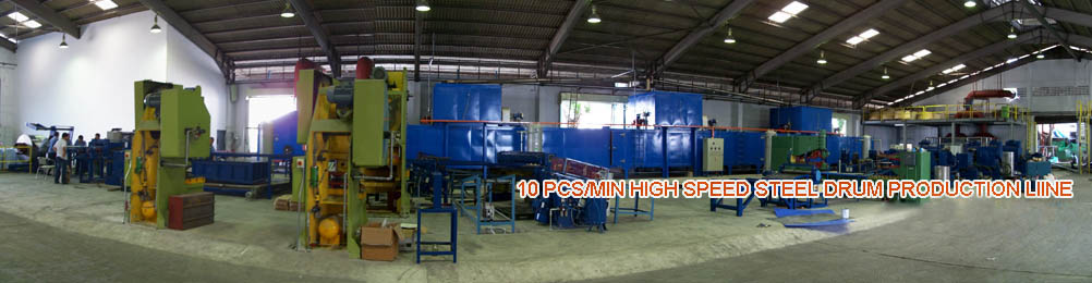
- 10PCS/MINUTE HIGH SPEED STEEL BARREL PRODUCTION LINE
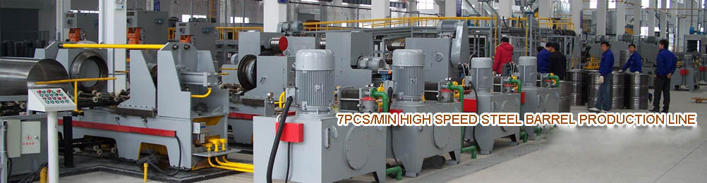
- 7PCS/MINUTE HIGH SPEED STEEL BARREL PRODUCTION LINE
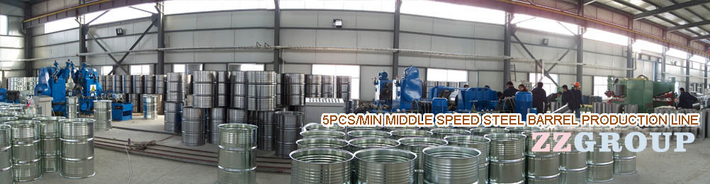
- 5PCS/MINUTE MIDDLE SPEED STEEL BARREL PRODUCTION LINE
- 1PCS/MINUTE LOW SPEED STEEL BARREL MACHINERY
Steel Barrel Manufacturing Technology and Equipment -Part Two
Five ) flanging machine for steel barrel manufacturing equipment
Drums flanging machine is used to complete the body of the machine flanging step .Flanging machine many types, according to the placement of a metal pail when working with horizontal and vertical flanging machine flanging machine ( horizontal axis represents the level of barrels , vertical refers to the barrel axis vertical ) ; press can flanging there are number of single-head flanging machine ( once only turn one end ) and double flanging machine ( one turn ends ) ; principle can be divided by flanging roller type flanging machines and extrusion flanging machine ; press can processing can be divided into a barrel and shaped barrel drum flanging machine flanging machine .
1 Roller with extruded flanging machine works
Roller flanging machine main working parts of two rollers . Work two rollers and drum body relative movement between the three ( rotate , pan, or swing ) , spinning wheel on the barrel body leaving the barrel body for plastic deformation to achieve the end flange .Figure 17-25 shows the principle of its flange . Flanging process , there are two sports , one roller relative to the barrel body for the movement , the barrel side pulls out ; Second, the barrel body rotates around its own axis , so that the edges can barrel cuffs . Barrel body rotational motion obtained in two ways : active and passive . Initiative refers directly from the barrel body rotates with the motor and reduction gear , rotating the flange by the barrel body with friction drive roller rotates. Passive refers to the motor and reducer drive rollers rotate, barrel body by the frictional force is rotated through the rollers . Profiled barrel for barrel roller profiling to make movement. Roller flanging machine flanging addition , there are a variety of functions such as necking of different metals and different thickness adaptability , and must be more common , but less accurate flanging .
Figure 17-25 rolled cuffs
1 - barrel up 2 - pressure roller 3 - pressure roller
Squeeze flanging machine is by two pressure plate along the barrel axis of the frame for relative movement to achieve flanging . It works as shown in Figure 17-26 . Two pressure plate relative motion by a hydraulic or mechanical drive to achieve. In flanging process, the sides of casks being squeezed, squeezed in order to assist the sides of casks to withstand pressure from the outside with a tire tool cover your tank wall . Flanging machine flange precision extrusion , simple structure , particularly suitable for multi- bead ( eg triple ) steel drums . But extruded flange when the tank wall to withstand a certain extrusion pressure , therefore , not be used for low strength extruded metal drums ( such as aluminum barrel ) for more than 0.6mm thickness in steel drums .
Figure 17-26 extruded flange
1 - cylinder 2 - Coupling 3 - pressure plate ? 4 - Barrel Box 5 - hanging through frame 6 - Bearings
2 drums flanging machine
Figure 17-27 shows a horizontal double-headed drum flanging machine . The machine is passive barrel body rotates Roller flanging machine . Its structure is symmetrical, work, flanging operation of both sides . Right half of the figure represents the highest position on the pressure roller , feed barrel body , showing the status of pending flanging ; expressed on the left half of the feed roller end position in the minimum wage , the state flanging barrels are completed . The following describes the working principle and working process :
Double drum Roller Figure 17-27 Schematic flanging machine
1 - upper pressure roller shaft 2 - Radial bearings 3 - upper pressure roller 4,9,13,16,17 - gear 5 - pressure roller Bay 6 - roller 7 - Spring
8 - Cam 10,12 - Pulley 11 - motor 14 - arbor 15 - worm shaft 18 - under the pressure roller shaft 19 - under the pressure roller
20 - Bearing 21 Torr, turn barrel means 22 - 23, Block Machine - Collar 24 - barrel box
( A ) the feed movement
Feed motion of the machine shown in Figure right part , by the upper pressure roller 3 for swing to achieve. Associated with the upper pressure roller platen roller shaft through bearing 2 is supported on a roller carriage 5 . Clockwise to push the cam follower roller 8 6 , the pressure roller bracket 5 A counterclockwise swing around the fulcrum . And the upper pressure roller 3 also will swing to the barrel , until the pressure roller shaft 1 is in the horizontal position is reached , thereby completing the feed motion . Then go to the smallest lift cam 8 , by the effect of the spring 7 , the pressure roller bracket 5 clockwise swing back into place , on the pressure roller 3 exits outside of the barrel , while the left part of the movement for symmetry . Then both ends of the barrel flange frame can be removed , the next one to be flanged barrel box to enter.
( 2 ) the main rotary motion
Main rotary motion of the upper and lower pressure roller rotation. The motor 11 causes the worm shaft 15 rotates , the right end of the worm shaft 15 and the gear 13 engages the gear 9 , so that the shaft 14 is rotated . 17 through the gear 16 and the engagement of the lower roller shaft 18 is rotated , the roller shaft is obtained under the pressure roller 19 the main rotary motion . When the upper feed roller swing down , the gear 4 and 17 gradually engages the rollers also won the main rotation. In this case , the lower barrel between the pressure roller a frictional force sustained , the pressure roller is driven about its axis of rotation , while the upper feed roller to complete the flanging effect . Flanging process, the ring 23 is to prevent axial movement of the barrel body , the upper ring has an opening , does not prevent the movement of the pressure roller .
Care, turn barrel means 21 supporting role in the flange front bucket frame is sent after flanging barrel box. Its structure and working principle shown in Figure 17-28 .
Figure 17-28 Torr, turn barrel device schematics
1 - barrel up 2 - prop barrel roller 3 - prop barrel rack 4 - Fulcrum 5 - cylinder
3 profiled barrel flanging machine
Flanging machine barrel shaped than round barrel flanging machine structure and principle be complicated. The following analysis of extruded profiled barrel flanging machine : Figure 17-29 illustrates a barrel shaped extrusion ( slider ) style flanging machine . Around the figure symmetrical structure , the work around is simultaneous action . Is shown in the left half of FIG drum frame to be cuffs state ; the right half shows the state at the end flange . It works as follows:
Figure 17-29 profiled barrel extrusion ( slider ) Schematic style flanging machine
1 - cylinder 2 - Pressure disc 3 - tube mold 4 - cone 5 - inside the slider 6 - outer slider 7 - spring 8 - forked lever
9 - link 10 - mandrel 11 - sleeve 12 - hem bar 13 - the pendulum 14,15 - Cylinder 16 - Alien barrel box
( 1 ) a feed drum frame and axial positioning
When the piston of the cylinder 1 is in the uppermost position, the piston rod fixedly mounted on the pressure plate 2 in the upper end of the drum frame placed on the platen and the lower mold 3 and the inner tube to trap the slide block 5 of the upper level. Then the piston downward , pressure plate fall, hold the barrel from the axial frame ( left figure ) .
( 2 ) protect barrels
The piston down the cylinder 14 , the upper left end of the lever 13 around its fulcrum pivot downward , through the cannula 11 and the connecting rod 9 the role of the forked upper end of the lever 8 is swinging bucket frame , the upper end of the forked lever and hinged outer slide 6 , so also will the outer slider 6 slide the barrel box until the hoop barrel box , reaching retaining barrel purposes.
( 3 ) flanging
The piston down the cylinder 15 , the hem bar 12 swings downward about the pivot left end and the middle hem lever hinged down along mandrel 10 , the upper end fixedly mounted on the spindle cone 4 bound down by the inner slide blocks 5 and mating tapered cone role within the outer barrel slide were forced to slide horizontally , resulting in complete barrel frame flange ( shown in the right half of Figure ) .
( 4 ) back into position to take barrel
The piston cylinder 14 upward , through a swing lever 13 , sleeve 11 , and the role of the forked lever , slide the outer slide , leaving drum frame return position. At the same time , so that the cylinder 15 of the piston upward , hem lever upwards swing , shaft and cone rising under the action of the spring 7 Slide the inner slide back into place . Then the cylinder a piston upward , upward pressure plate has flanging barrel box for easy removal.
( Six ) corrugator machine with bulging tendons
Barrel body roll out across multiple machines with corrugated corrugated machine with bulging tendons bulged in the middle of the barrel body reinforcement ring two ribs, raise barrel strength.
Corrugated machine with bulging tendons machine working principle is the same , the structure is very simple . They are the shape of the barrel body set on the rotary spindle through with corrugated ( or ribs ) cross-section along the barrel body grooved rollers radial feed , the feed process, to produce cold spinning barrel body material deformation .Spinning wheel to process, resulting in three directions of movement , that is, along the barrel body ( or spindle ) radial movement of the roller along the axial direction of the spindle movement and rotational movement of the roller itself . Grooved roller surface knurling or swelling due to the depth of rib different sizes . Roll groove shallow and dense , Beading deep and wide.
( Seven ) sealing machine
Sealing machine structure principle and three cans or two cans sealing machine works the same. If you use multiple ( triple ) curling sealing machine , just after the original double seamed sealer adds a seaming .
( Eight ) leak testing machine
Leak testing machine is used to test the tightness of the barrel of the machine. Leak testing generally in two steps, namely before and after the test leak leak . Before the leak before sealing the barrel body refers leak testing , mainly to check the barrels are welded seams welding quality and tightness. After the leak is bottom of the barrel , barrel after sealing the top ends of the inspection , testing and sealing bead sealing quality .
Leak testing machine works: it is the drums sandwiched turntable ( with a single wheel and dual wheel ) between the clamp and sealed with rubber gaskets ) , and then filled with a certain pressure of gas or liquid, to see if there is a leak .
Figure 17-30 shows an airtight leak leak testing machine devices. It is used to test the barrel body or the entire empty bucket . Will be made of empty barrels to leak testing machine, sandwiched turntable 3 . The turntable rotates, the compressed air into the drums , the drums if the leak , the pressure will drop, so the connection with the tank vent diaphragm movement , for automatic detection. The drums pressure testing, after a turn around by the automatic lifting device and the guide groove to the next channel packaging process ( loading ) or as an empty product automatically discharged .
Two , pails manufacturing equipment
Pail manufacturing process route and the corresponding equipment are as follows : Cut cutting ( shearing machine ) → milling ( milling machine ) → roll forming barrel ( barrel roll forming machine ) → Weld ( Weld machine ) → welds polished ( polishing machine ) → Belling ( belling machine ) → opening full crimping ( crimping machine ) → barrel Beading ( Beading machines ) → bottom flange ( flanging machine ) → bottom hem seal ( double volume edge sealing machine ) → lug welded ( lug welding machine ) → leak test ( leak testing machine ) → install loop handle ( portable ring mounting machine ) → assembled intussusception , processes shown in Figure 17-31 . Its processes with the aforementioned metal drums ( storage barrels ) manufacturing process almost.Manufacturing methods and other metal container manufacturing method substantially the same .