STEEL BARREL
STEEL BARREL PRODUCTION LINE
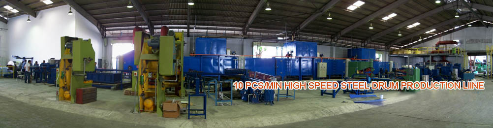
- 10PCS/MINUTE HIGH SPEED STEEL BARREL PRODUCTION LINE
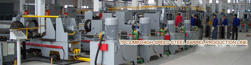
- 7PCS/MINUTE HIGH SPEED STEEL BARREL PRODUCTION LINE
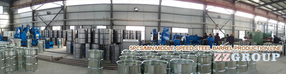
- 5PCS/MINUTE MIDDLE SPEED STEEL BARREL PRODUCTION LINE
- 1PCS/MINUTE LOW SPEED STEEL BARREL MACHINERY
Tin Soldering Three Pieces Making Technology and Equipment
Metal containers refers to the metal sheet material made of thin-walled packaging containers. Many different types of metal packaging containers , from the shape and structure of the points, mainly cans , tubes, boxes, buckets , hoses, boxes steel barrel production line.
Metal cans for food packaging is a typical metal packaging containers, its structure is mainly two types of cans and three cans . Two cans have deep drawing drawing two cans (DRD) and thinning of the stretched two cans (DWI) two kinds ; three cans there soldering three cans, three cans resistance welding and bonding three pot three.
Metal drums and metal hose in the food, chemical and commodities increasing the amount field . In addition , the metal foil packaging as a packaging also has a wide prospect to get people 's attention. To this end , this chapter focuses on three cans, two cans molding machinery.
Section Metal cans container forming machinery
This section only canned food , beverage packaging three cans and two cans container metal packaging and processing machinery manufacturing technology to analyze and presentation.
One , three cans of Manufacturing Technology and Equipment
Is defined by three cans cans , tank bottom and lid ( cover ) three consisting of metal cans.
( A ) Soldering three cans of Manufacturing Technology and Equipment
Solder three cans by shape of round cans , square cans, ladders ( cone ) horseshoe -shaped cans and cans . Among the most widely used circular tank , the largest amount , the following example describes a circular tank of its manufacturing technology and equipment .
1 solder three cans of manufacturing processes
Solder three cans manufacturing of cans , lids , cans and lids combined three processes.
Cans machining process: tin plate cutting shearing bending → → → side cutaway Cutaway and folded into a round → → → Crush → coated welding flux welding at wiping solder tin scrap → → cooling → flanging → cans complete.
Lid of the processing process: tin plate shear oiled material → → → punch cover curling → → drying → lid dispensing process is completed.
Cans cans with lid formed by combining machining process: plus lid cans into → → → double seamed cans sealing process is completed.
2 cans Processing Machinery
Cans with semiautomatic and automatic processing in two ways .
( A ) semi-automatic manufacturing round cans of special equipment
Round cans semiautomatic manufacturing equipment including shears, cutaway Cutaway machine, side folding machine, into a circular machine, overcome machines, soldering machines and flanging machines.
Shearing is used cans tinplate conduct of cutting machines. Cans are often used guillotine shears and circular knife type two, which round knife most widely used. Round knife shears , also known as circular shears , the upper and lower two opposite rotating knife shaft of each mounting a disk cutter and pressure roller , the upper and lower knife blade in contact with the disc plane phase delivery , constitute a continuous scissors, cut sheet was separated therebetween .
Notching notch machine, side folding machine, overcome the machine , uses a small crank press structure , together with the corresponding tooling to achieve its technology capabilities. Notching machine is used to cut the missing blanks in the tank body parts cut bevel angle at both ends and gaps ; side folding machine is used to bend the occlusal vertical seam cans hooks ; overcome the machine is used to overcome and pressed cansafter the longitudinal seam into a round hook engaging portion , so that the longitudinal seams constitute securely connected .
Into a circular machine is folded and overcome the side of cans rolled into a cylindrical billet machine. Produced three cans usually roll into a circular machine , roll into a round by three law to make cans ideal slab curled into a cylindrical shape . By adjusting the distance between the roller and the roller , can be changed into a round cans curvature of the slab .
Soldering machine is to use tin solder the seam weld machine. Overcome when the longitudinal seams , hand- painted flux at the seams , and then soldering machine soldering .
( 2 ) automated manufacturing round cans of special equipment
Round Can Body adopt modern manufacturing automatic continuous production line is generally used when automatic duplex round knife cutting machines, automatic joint cans making machine , automatic flanging machine high efficiency of the machine.
Automatic double- round knife cutting machines, circular blade shears by two mutually perpendicular dispositions. One of the circular blade shears complete blank cans length cutting, shearing completed another round knife cutting width . Each has a pair of shears on mutually reverse rotation of the upper and lower knife shaft , shaft mounted multiple pairs of circular knives , and each has a conveyor and a workbench. Tinplate in the first round cutter shears work bench by the conveyor feeding along the side guide plate , after cutting disc was cut into strips between the discharge to the second connection before shears workbench by the band pawl chain conveyor to a second shears , and through the upper and lower disc cutter shaft , accepting cut again , get to meet the size requirements of the tank physique blank .
?
Figure 17-1 Schematic cans joint manufacturing machines
1 - feeder China; - bender ; 3 - Cutaway notch device ; 4 - side folding device ; 5 - cans molding machine ; 6 - Shaft
7 - flux coating device ; 8 - preheating device ; 9 - soldering machine ; 10 - rub tin device ; 11 - cooling section
Auto Union cans manufacturing machine can complete physique billet rolling cans and cans will be welded longitudinal seam weld tin work . The machine consists of automatic joint cans forming machines and soldering machine. Cans forming machine mainly consists tank physique blank library , vacuum feeding device , bending processing device , Cutaway notch device , cans physique feed conveyor , side folding device , forming overcome the device and the guide shafts and other components. It can complete the slab from the cans into the hopper to complete flatten cans occlusal interface multi- channel tube manufacturing process . Soldering machine consists of coating flux , preheat , solder, tin wiping crumbs, cooling and other devices , used tin cans welded seams and cleared the whole work . Is shown in Figure 17-1 cans joint manufacturing machine , feeding usually vacuum feeding device, the slab from the database sent ; treatment using roll bending device, so that when bent through the slab , reducing the flexibility and stress relief plate concentration phenomenon ; Cutaway cutaway , side folding adopt eccentric crank mechanism driven special mold to complete ; into a round roll into a circle using some method , some use synthetic wings -in holding circle method ; various soldering processes are completed using automatic welding equipment , cans machining process shown in Figure 17-2 .
?
Figure 17-2 cans process flow diagram
1 - Feeding China; - bending process ; 3 - Cutaway notch ; 4 - end fold bending ; 5 - into a round crimp ; 6 - Tu welding flux and preheat
7 - Solder ; 8 - heating ; 9 - wiping crumbs ; 10 - Cooling
Automatic flanging machine is using a mold is applied to both ends of the circular cylindrical tank pressure extrusion , to form a bell mouth valgus machines. Flanging machine shown in Figure 17-3 , flanging for cans and bottom of the tank ready for double seamed sealed condition . Cans production line using a rotary automatic flanging machine , a common four -style , six -in other models . Rotary flanging machine is mainly from the base 1 , flanging drive 2 , flanging die 3 , sliding tube 4 , into the tank track five , star prop tank rounds 6 , 7 and joystick gear 8 and other components. Flanging , the cans into the tank by the track 5 enter flanging machine , one by one in a star prop tank round 6 round slot positioning . Round 6 took care cans cans flanging die 3 and the corresponding synchronous rotation, rotation of the cam drive flanging die three cans for advancing to the next and back away from the sport . Both sides of the flanging die when advancing to the cans , cans extrusion mold edge port end it turned out, to meet the requirements , the flanging die and return situ separation cans , cans have been flanging transmitted by the supporting cage wheel to the bottom of the tank track by the discharge .
?
Figure 17-3 Rotary flanging machine
1 - base China; - driving device ; 3 - flanging membrane ; 4 - sliding tube ; 5 - into the tank track ; 6 - star prop tank round ; 7 - joystick ; 8 - gear
3 system capping machine
System cover, first tinplate cutting board with a wave machine cut into the pressure waveform edge slats to improve plate utilization , as shown in Figure 17-4 . Slats in the red cap with a wave machine punched by a stiffening ring , flat and beveled cap billet form , and then curling rolling bodies roll its edge , it will become a crochet cap , shown in Figure 17-5 . Crochet in the cover note sealant coating , drying to form a flexible film , complete lid manufacturing and processing .
Figure 17-4 Figure 17-5 lids irrigation using waveform slats cover structure
Lid manufacturing equipment has two kinds of semi-automatic and fully automatic , fully automated manufacturing equipment including lids pressure waveform cutting plate machine, automatic punching machine cover , lid crimping machine, plastic injection machine , dryer and so on.
Cutting plate machine , also known as pressure waveform scroll shears, belong hyperbolic crankshaft -type presses, dedicated to the cut edge of the sheet with the waveform . The sliding seat is mounted waveform cutter knife , the corresponding fixed blade knife seat bottom mounted to the waveform .
Automatic punching machine from the feed tray cover , automatic feeding device , dies waste discharge roller , cover throwing device and connected directly with this lid crimper components. Chong cover mechanism adopts double column tilting lift ( press ) agency.Blanking lid mechanism punch mouth equipped with safety devices to prevent the two cover both fall into the crimper . If two or more double feed condition , the clutch will automatically effect , punch stop ( crimper discharge outlet , also has the same safety device ) . Some punch machine cover on the surface to prevent the cover pattern, but also a high frequency heating means for heating the blank before stamping .
Punched by the punching machine cover lid , perpendicular to the plane of its edges with the cover , is not conducive to the process after the closing. To improve the sealing bead conditions to prevent the glue dispensing spill , the need for crimping the lid , the lid around the inwardly bent about 50 ° . Round Can crimping machine has a single wheel and wheel bead two, namely capping machine with single or dual punch punching machine is equipped with a lid . Figure 17-6 shows a two-wheeled curling agencies, the outer edge of the disc 2 fixed inner crimping die 3 , base plate 5 is fixed to the outer edge mold 6 . The curling curling die mold and formed between the outer chute 7 crimping , possession or 180 ° or 270 ° of arc . The width of the chute 7 wide inlet end of the cover , the cover is narrow at the outlet , was continuously changed. Disc 2 after driving by the motor via reducer for rotary motion . Crimping machine capping machine installed in the punch after punch by chute and discharge chute cover machine lid dovetail . Punching machine punching out of the cover lid from falling inclined chute , conveyor belt directly or through accelerated into the crimper . Lid into curling chute , driven by the rotating disc curling chute for rolling along the road , the road in the same time by crimping die extrusion, forced inwardly curved lid edges . To complete the outlet end cap crimp discharged to the collector or by conveyor belt to go .
Figure 17-6 wheel automatic crimping mechanism
1 - Sink cover China; - disc ; 3 - the curling die ; 4 - cover collector ; 5 - base plate ; 6 - outer crimping die ; 7 - Chute
Lid plastic injection machine is to cover part of the injected sealant crimping equipment . It can press the dispensing dispensing width and pressure to ensure that the tank lid sealing body connection . Round lid plastic injection machine with a single head and four , they were a dispensing nozzle and four dispensing nozzle , where four plastic injection machine is dispensing functions combined machine and dryer . Figure 17-7 shows the four plastic injection machine , it mainly consists of lid feeding device , dispensing mechanism , drying box , frame , transmission, control mechanism and other components.
Figure 17-7 four plastic injection machine diagram
1 - Under pressure head ; 2,3 - star wheel ; 4 - cover bore ; 5 - dispensing nozzle ; 6 - needle ; 7 - on the head ; 8 - mandrel ; 9 - cylindrical cam ; 10 - glue tube ;
11 - assigned axis ; 12 - distribution box ; 13 - drying box ; 14 - pillar ; 15 - Screw ; 16 - Cover discharge chute ; 17 - heater ;
18 - Control Panel ; 19 - lose hose ; 20 - plastic storage box ; 21 - Pressure Pumps
Four plastic injection machine work, the lid put on the cover bore 4, star wheels 2,3 be sent to the device under the pressure dispensing head 1 , the dispensing device has four sets of plastic injection nozzle and the upper and lower indenter . Dispensing needle 6 by the mouth of the fixed cam 9 Control and opened and closed . Pressure pump 21 into the compressed air reservoir tank 20 , the sealant hose 19 from the input to the distribution box 12 and the dispensing nozzle 5 . Nowadays dispensing head a rise in pressure in the lid are the upper and lower pressure head between the upper punch 7 driven by the rotation, plastic injection needle dispensing nozzle 5 open . In the dispensing process, the lid switch two weeks in order to prevent leakage Tu . After injection plastic lid , set aside by the star wheel , into the drying tank dry.
Dispensing lid after drying box through the transmission mechanism into the heating and drying , cooling and solidification and transported to the next step . Figure 17-8 shows a dual-channel structure of drying box , transfer agency will lid ( jar ) adsorbed on a magnetic stainless steel belt , the hot air drying and then into the upper part of the cooling channel for cooling , to complete the entire drying process . The drying process, the lid ( or tank ) side down , air flows from the inside to the outside of speed , to achieve efficient heat transfer . Drying curing time is about 3 ~ 5s. Since the magnetic belt , it will not cover or cans dumped , it will not appear disorderly phenomena .
Figure 17-8 dual-channel dryer ( drying oven ) Schematic
1 - Cooling load conveyor China; - cooling channels ; 3 - heating Road; - Remove the conveyor ; 5 - Plug lanyards ; 6 - main conveyor
7 - double belt conveyor ; 8 - caps or cans in the box to run
4 cans combined with mechanical seal with lid
Cans with lids good system , you need to combine the two into a tank containers.Generally use two double seamed sealed way to combine the two to make it sealed.Seamer There are two types of single and bulls .
Seamer mainly by automatic feed tank unit , automatically sent to cover and capping device , curling sealing devices and other components . Crimping sealing device is a seamer core device seamer may refer to the specific structure of packaging machinery professional manual .
Seamer work, plus lid cans after being sent seamer head positioned under the pressure , under pressure head by a cam-driven rises together with the upper ram caught the lid cans , then roll seal head on the implementation of double seaming lid cans sealed .Seaming machine head mounted prescribe ( per channel two seaming rollers ) of four seaming rollers , the first of two volumes for head and said first sealing bead rollers , and then complete the second volume crimping rollers work closure operations. Figure 17-9 is a schematic double seamed sealing operation . After completion of sealing bead , under the pressure head down , empty discharged by the discharge means . During crimping seal when seaming rollers for rotation relative to the tank , it is also central to the tank for radial feed movement. By the specialized agencies to achieve its movement .
Figure 17-9 Schematic double seamed sealing operation
Seamer materials can also be used to fill the tank after capping . Crimp seal with the sealing device seaming track is now applied , this rail-mounted sealing , long life, work more efficiently.